I’ll go straight to the point.
In my free time I’ve been designing a linear voltage source. What’s that you may ask? It’s a type of power source that has the property that it adjusts its voltage in a way that linearly mirrors some input, so it’s behavior looks something like this:
V = kX + b
Where x is some input and k and b are some constants.
However I wanted to challenge myself and have the source also be bipolar, that is to say, it posseses the ability to provide both positive and negative voltage levels. This is useful when you work with operational amplifiers (to work with signals that hover around ground levels and not suffer distorsions), or in control circuits where some exit needs to be deactivated quickly. Finally, I wanted to add a fixed 5V output, since 5V is the voltage used for digital electronics.
Also, I realised Hugo can turn diagrams into SVGs via a library called Goat, so you’ll be seeing these funny looking block diagrams everywhere in this post.
In theory
Design principles
A voltage source is generally composed of the following components:
- AC Source: Electricity doesn’t come from nowhere, it needs a power source where electrons can be forced to produce work. The simplest solution is connecting your circuits to the power grid; however this type of electricity is both very big and constantly changing direction (that’s why it’s called Alternative Current). A transformer can lower the voltage from the power grid to something more managable, though it stays as AC.
- Rectifier: A rectifier is a type of circuit that converts AC power to DC, in other words, it forces current to go in one direction. But a rectifier doesn’t give you a fixed level of DC, it still fluctuates in intensity.
- Filters: This part of the circuit is just a big capacitor, its purpose is to stabilize the current rectified previously into a fixed level. This is done because a capacitor resists changes in voltage, which is exactly what is happening with the unregulated DC from the rectifier. Sometimes you see a smaller capacitor along side it, which serves a similar function, but it regulates changes that the previous capacitor couldn’t filter out.
- Voltage Control: This is usually done with a special component that uses some transistor magic to output the voltage desired. Because of conservation of energy, it cannot provide a bigger voltage that the input it is given, and large Vin-Vout differences can result in heating, so a heatsink is attached to it to regulate its temperature.
- Control Input: Usually a potenciometer (a variable resistor) is used and connected to some feedback mechanism with the Voltage Control. If you want to get fancy, digital controls can also be used. Either way, the bigger the input, the larger voltage you recieve.
Since my voltage source has both positive and negative voltages, the previous block diagram repeats for the negative counterpart.
Now you may be asking, how did you manage the Voltage Control part? Well, this where the heart of my project comes in: let me introduce you the LM317 and LM337 voltage regulators. These bad boys can output 1.2V to 37V using just two resistors! They also have built-in current limiters, thus preventing any blow-outs that may happen by accident. Their basic circuit is the following:
The secret of these components is the fact they use a voltage divider to set
V_out. A voltage divider is a pair of resistors in series that distribute the
voltage provided to them based on how resistant they are. In this case, we’re
using this tecnique to obtain the initial voltage, V_out.
The voltage between the V_out and Adjust terminals of the component is set
to 1.25V, and this voltage is the same voltage that is passing current through
the resistor R1. Because of Ohm’s Law1, the current that passes through R1
will be some fixed amount, which coincidently also passes trough R2, our
potenciometer. The arrow you see on its right is the adjustable knob of the
potenciometer, and it is connected to the upper connection so that the value
of R2 ends up as the same as the value we adjusted.
After clearing some stuff, the amount of voltage we get follows this formula:
Vout = 1.25( 1 + R2 / R1 )
We can play with the ratio of R2 and R1 to get maximum voltage we want for our power source, and design everything around it!
The datasheets also provide a more robust design that prevents discharges from going inside the regulators and smooth its operation, but I won’t draw them since I’m lazy and you will see them later.
Rectifying AC to DC
As I mentioned in passing before, a rectifying is the name for converting AC power to DC. The amount of voltage that is converted is the same as the difference between the peaks of the AC wave. How exactly do you measure this voltage? It’s simple, though it requires a little of theory.
AC is commonly measured in something called Root Mean Square, which in layman’s terms it is a type of mean where you add up square of each element then divide between the number of elements, then the square root of that is the RMS value. For a continious function an integral is of the square of the function is used instead. RMS is used for measuring AC sine waves because if you use a normal mean, then you get 0, which doesn’t make sense. The RMS of a sine wave gives the amplitude of the wave, divided by sqrt(2). In math lang:
Vrms = Vpeak / sqrt(2)
If your country provides you a voltage of 127V RMS, then that means that for a small moment, your appliances recieve 179.6V, then -179.6V a little bit later. This amount of power is too much for our little electronics and small motors to handle, so this voltage needs to be brought down with the use of a transformer that can take this voltage, then with the magic of inductance and magnetism, provide a lower AC voltage that can be handled more safely, at the cost of giving a higher current value at the exit.
The type of rectifier I used is called a full bridge rectifier, which is the most common type of rectifier that is actually useful, because it actually uses the full power of the transformer every half cycle. It looks like this:
The triangles with top-hats you see is called a diode, which it’s job is to only allow current to pass through when there is a higher voltage on its anode (the base of the triangle) relative to its cathode (the lined top), of at least 0.7V; anything else and the diode stops the flow of current. Because of their arrangement, current is always allowed to go through back the transformer from one of the two diodes, and escape from the other side. It’s something quite interesting I invite you to investigate for yourself, as my diagrams don’t give enough credit to how awesome power electronics is.
The other thing that I added here is the filter: just a single capacitor big enough to charge when provided with voltage higher than the one it is storing, and discharge slowly via the load when it isn’t. Something I read on my power electronics book 2 recently is that because of this charging and discharging action, the voltage value being rectified will oscilate between a minimum and a maximum instead of the 0 to peak oscilation you would see without the filter being there. In general, a bigger capacitor means a higher discharge time, so the range of DC voltage we get becomes more precise.3
Isn’t that great?
In practice
It is great, until it isn’t.
The transformer used
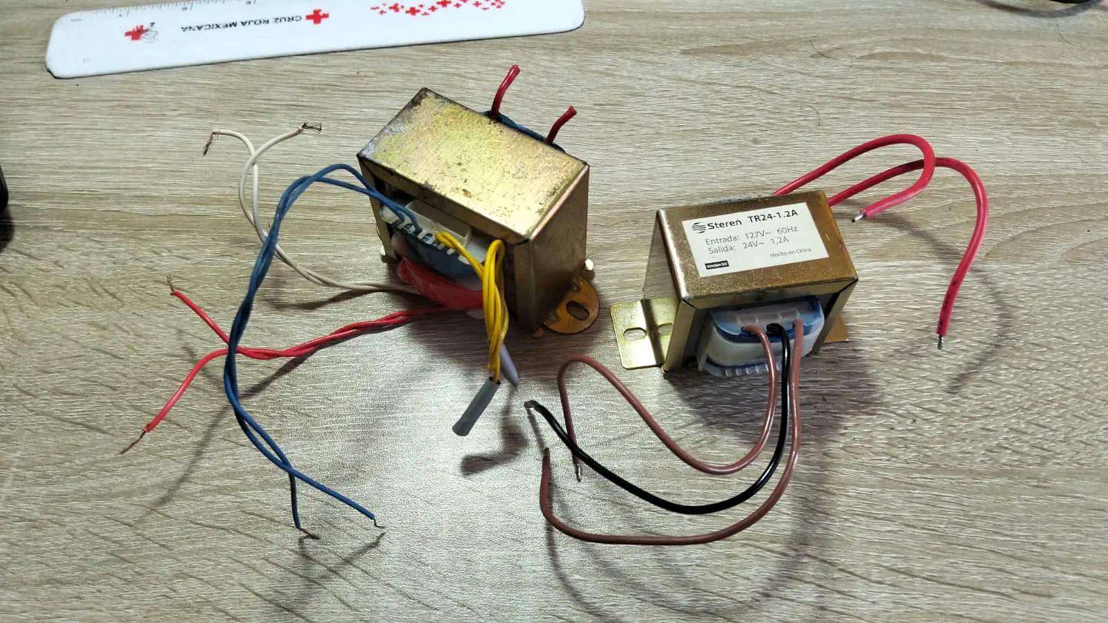
The two transformers I used during this project. The left one was the original one but its input is short-circuited, so it is unusable. The right one is the replacement and the one I ended up using.
Let’s talk about the most important thing first: The power source, aka the transformer. Orignally I wanted to use the left transformer as it was given to me by cousin who gifted me with leftover components for to recycle when he finished his mecatronics degree. After testing it with a series circuit4, it turns out I discovered two things:
- The outputs gave me 36.6V RMS on the red and white outputs (51.7V when rectified), and 8V RMS on the blue output (11.3V amplitude).
- The input is short circuited, and would always flip my home’s breakers when plugged without the series circuit.
Which meant the original shematic I designed (and honestly quite a terrible one) wouldn’t work unless I redesigned some things for the new transformer.
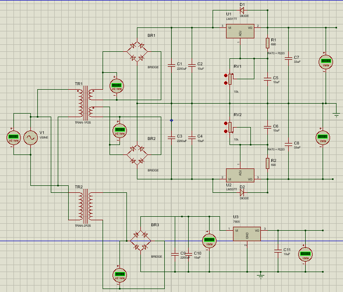
Issue number one of this design is the double use of rectifiers for the bipolar voltages: I could have rectified the extreme poles of the two 36.6V RMS outputs and use their union as a central tap, therefore saving me 4 diodes. The second issue is the limitation of the LM317 and LM337 can only savely regulate a |Vin-Vout| difference of 40V. This meant that while I could design it for the 30V DC I wanted for each pole, I needed to think about the opposite scenario: what happens at the minimum of 1.25V when the variable resistor is set to 0? If I wanted to bring 30V into the scene I needed to place a voltage divider before the regulator, and those things consume power, leading to an inneficient use of electricity.
And so, I purchased the transformer on the right from an electronics shop that bought it from Steren, which is rated to provide 24V RMS and 1.2A RMS. After testing it with the a capacitor of 3300uF, my voltage source can now provide…
20.1 VOLTS PER SIDE?!?!?! That’s lower from what it is rated, but fine, compromises are ok. I think.
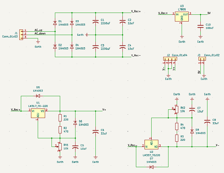
Thus, my final schematic is this one, which I designed in KiCad:
Designing for a lower output voltage
I used this design from Unicrom
as a reference, and noticed I could use the extremes of the transformer
to rectify them, then connect the central tap to ground to obtain my bipolar
voltage. What I labeled as V_Rec+ and V_Rec- are 40V apart, but when
measured in reference to the central tap, they’re at 20V. That’s a lot better
for the regulators to handle! Also, V_Rec+ feeds both the variable positive
voltage and the fixed 5V regulation, done with the help of a
LM7805.
Finally, I had to adjust the new regulation resistors to a new maximum value of 18V. Solving R1 from the regulation equation and using 10k potenciometers, the resistence of R1 needed to be 746 Ohms, a resistor whose value does not exist on the market. I ended up summing a 470 and 220 Ohm for 690 in total, so now my source can theoretically provide up to 19.36V in each direction.
Protoboard prototype

The prototype of the power source with some scattered stuff on the desk
I won’t go into detail of how I assembled the prototype of the circuit, since it’s boring and I don’t have the writing juice to describe placing wires and components neatly. I will mentioned that I used 1 Watt resistors to act as a load when building out each step of the power source, as to not overload the transformer with a much lower current than it was intented to work for.
Most of the wires were already cut due to my digital electronics course, so I only had to select the ones that fit were I needed them to connect to.
During testing of the first transformer, some of my clippers got burned, so they are now on clamper duty until I make the PCB.
Speaking of a PCB…
Going from prototype to something useful
We now reach the present, where I finished designing the PCB for the power source. What’s that you ask? PCB stands for Printed Circuit Board and it’s a plate of one or more layers of copper that are cut in such a way that they form the topology needed for a circuit to work. This technology revolutionized electronic systems by creating a standard way for manufacturing circuits at scale. Components can either be soldered in a through hole (THT), or mounted on the surface (SMD) when connected to the PCB.
In Veracruz, it is rare to see a PCB machine that can print more than one layer, so I had to design mine with the limitation of using the Top Copper layer. Here is the final result:
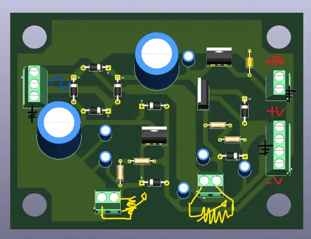
3D render of the PCB for my power source, with the terminal block annotated to where they connect to
The biggest problem I faced was connecting the ground to everywhere it needed to go, which ended up with me having to go below the rectifier to reach the positive voltage regulator and the output ground connection, while keeping it relatively big so it’s voltage value doesn’t change much. Ideally, I would have reserved the Bottom Copper exclusively to ground connections, and the Top Copper to the rest of the circuit. Compromises are ok, I think.
And that’s where I’m at! I’m looking for PCB services in my city, and I need to check if my school’s PCB printer room is open right now, or wait until the semester starts to use it. A friend of mine is 3D printing a cabinet that will hold everything inside, so I need to find the outlets needed. After that, I will need to solder everything to the board without the tin melting over pathways and causing a short circuit.
But’s another can of worms I may update you on in the future. That’s everything for now, so in case I don’t see you, good morning, good evening and good night!
Please forgive my lack of blog posting
-
Ohm’s Law states that Voltage is directly proportional to Current times Resistance, so knowing two gives you the missing third. Mathematically it is written
V = IR↩︎ -
Power Electronics Circuits, Devices and Applications. Muhammad H. Rashid. Chapter 3.13: Rectifier circuit design, Example 3.20 ↩︎
-
You could calculate the capacitance needed to maintain a DC voltage on a certain level with some certainty, but it’s very complicated and I won’t go into it here. Please refer to the example in Rashid’s book to see how you can calculate it, only to find no such capacitor exists and you need to obtain one with a similar value, connect many in parallel, or in series. ↩︎
-
A series circuit is just a socket coord connected to a lightbulb on one end, which is connected to another wire or a pair of clippers, while the other end of the coord is left bare. The idea is that if the two ends are short circuited, the lightbulb turns on, taking the power that would have gone to the tested circuit instead. ↩︎